Click here for more information about preload selection.
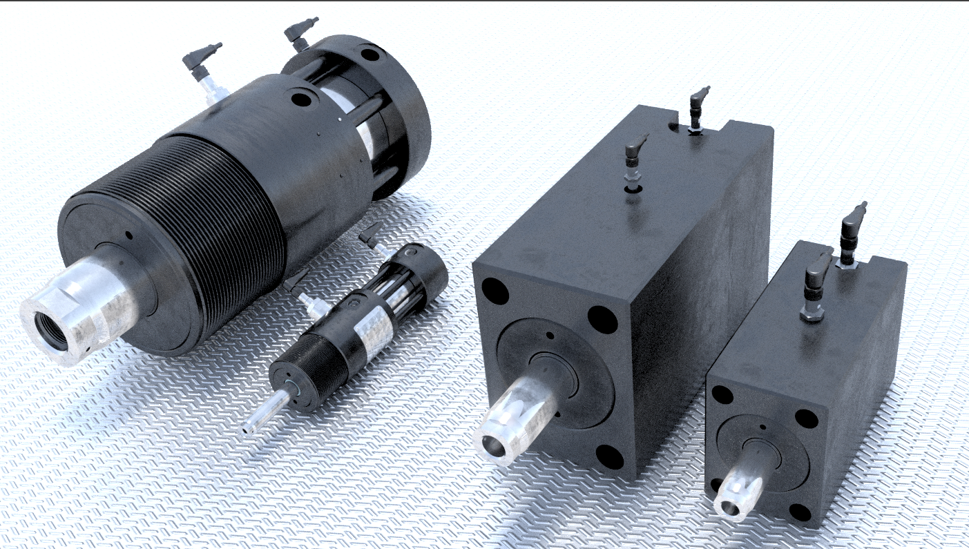
CYTEC CYPULL GENERATION II
Locking core pulling cylinders are a result
of profound product know-how gained over many
years by CYTEC Zylindertechnik GmbH. They have
been used successfully for decades in the
plastics processing industry. The latest generation sets new benchmarks for economic production of complex and highly specialised solutions in
the mould design and construction.
CYPULL cylinders enable technically elegant and sim
-
plified concepts, combining high forces with compact
structural shape. Significant advantages for the produc
-
tion process: reduced construction, cost and manufac
-
turing effort, minimised susceptibility to trouble and
longer production cycles.
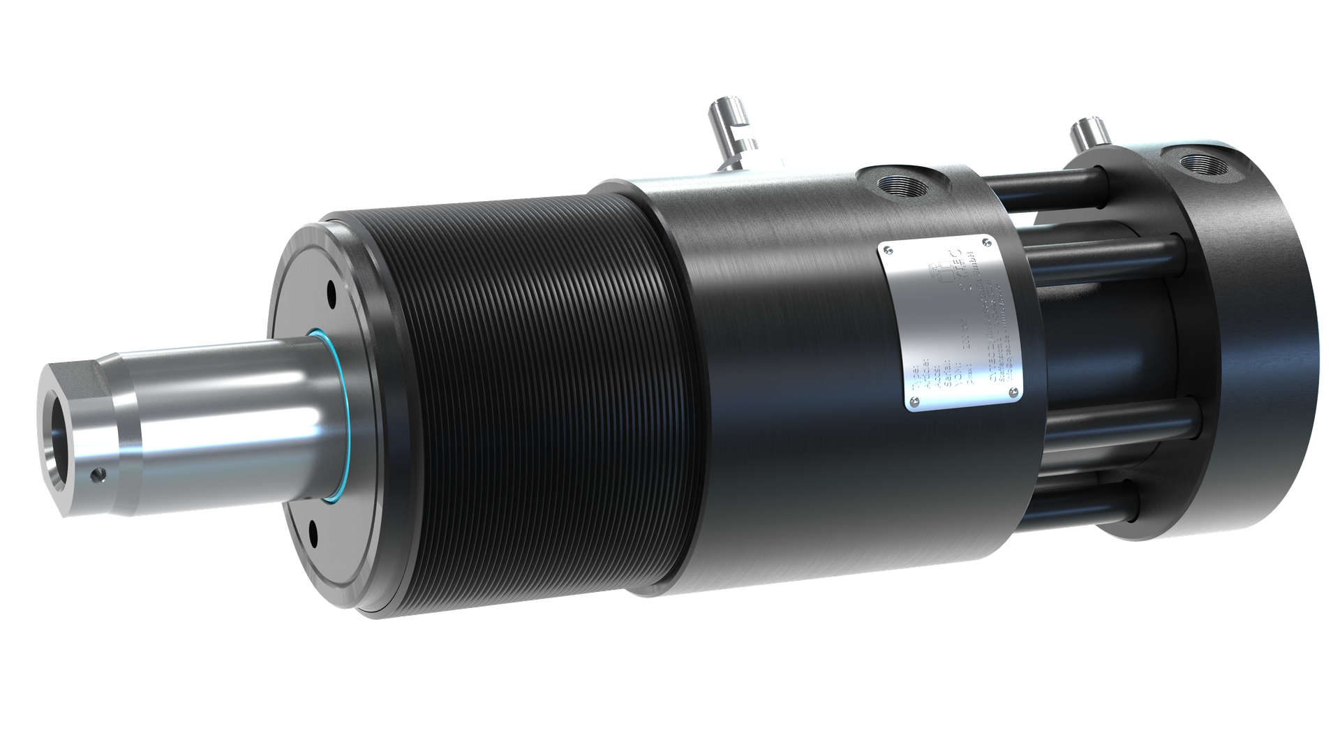
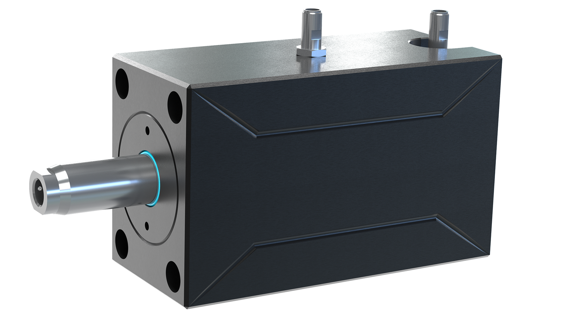
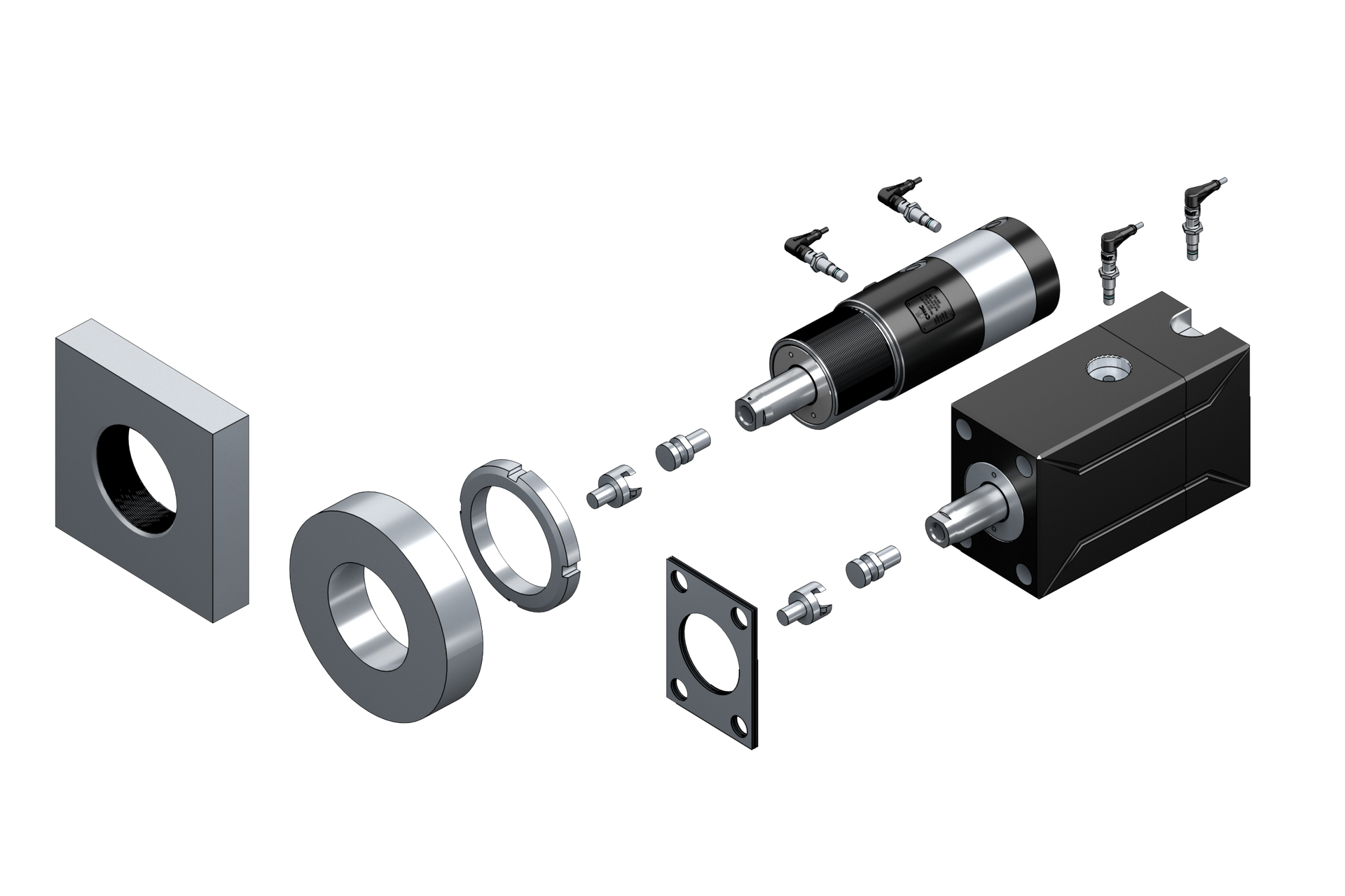
The cylinder structure, optionally available as round
or block design, is extremely rigid. This guarantees con
-
stantly high workpiece quality and maintenance-free
operation along with reliable productivity.
For almost every application an appropriate CYPULL is
available, supported by a wide range of options and
accessories (function and status monitoring, mounting
solutions etc.).
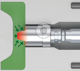
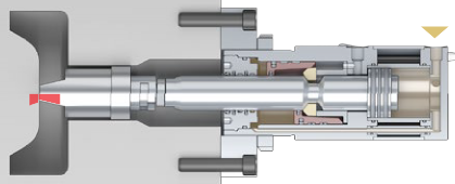
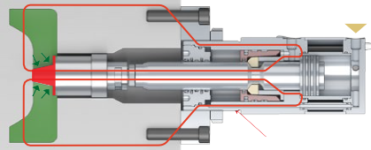
Phases 1 to 4:
The mode of operation is similar to
series CP-H...-L, but here the segments create an additional preload
to provide that the core touches the
mould surface reliably.
The locking slide and segments have
a characteristic cone shaped contour
which enables the piston rod to lock
within a defined tolerance range.
Elasticities which can occur commonly
in the mould construction are compensated.
This tolerance range in the final
position can reach up to 1 mm
stroke.
The self-inhibiting locking is
maintained permanently and as a
result the pressure supply is not
necessary. In this range a preload is
generated that guarantees reliable
operational process and high workpiece quality.
The red curve displays the force distribution as it is achieved in the locked
position with positive lock. Core and
piston rod withstand the high counter
pressure during the following injection cycle definitely. The core does
not recede!
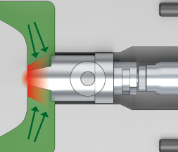
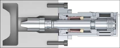
completely exposed core, not touching core
(series CP-H..-L)
Phase 1:
In the initial position the piston rod
is retracted.
Phase 2:
The piston rod is extended by applying hydraulic pressure on the piston
side. As soon as the piston reaches
the final position, the locking slide
moves axially over the three-dimensional locking segments and
pushes them into the annular groove
of the rod . So the segments are
fixed in radial and axial direction.
The piston rod is clamped with
positive lock.
The hydraulic pressure is switched
off, providing a maximum of operational safety.
Phase 3:
During the injection process the core
is pressurised, but it doesn't recede
in any case. The piston rod always
reaches the defined final position.
The hydraulic pressure is branched off
with a by-pass drilling from the main
supply ports for extending and retracting, enabling very fast stroke cycles.
Phase 4:
The release port is pressurised, the
piston rod unlocks and moves back to
the initial position.